Module - 5: Special Function ICs
On completion of this module, you will be able to:
- Understand IC-566 Voltage Controlled Oscillator (VCO)
- Understand Timer IC-555
- Understand IC Voltage regulators
- Understand IC-723 general purpose regulator
- Understand Frequency to Voltage and Voltage to Frequency converters
Introduction to Memory
- In computer, memory is the most essential component of the normal functioning of any system.
- Memory is any physical device which is used to store data, information or instruction temporarily or permanently.
- It is the collection of storage units that stores binary information in the form of bits.
- The memory block is split into a small number of components called cells.
- Each cell has a unique address to store the data in memory, ranging from zero to memory size.
- for example if the size of computer memory is 64k words, then the memory unit have 64*1024 =65536 location or cells and the address of the memory cells varies from 0 to 65535.
- The following figure represents the classification of memory

- The Primary Memory is also known as system memory, whereas the Secondary Memory is called the Storage.
Random Access Memory
- RAM is a read/write memory where the data can be read from or written into any of the memory locations regardless of the order in which they are arranged.
- Therefore, all the memory locations in a RAM can be accessed at the same speed.
- RAM is used to store data, program instructions and the results of any intermediate calculations during the execution of a program.
- RAM is available in the form of ICs as well as in the form of plug-in modules.
- The plug-in modules are small circuit boards containing memory ICs and having input and output lines connected to an edge connector.
- Depending upon the nature of the memory cell used, RAM are devided into two types of RAM, namely static RAM (SRAM) and dynamic RAM (DRAM).
Static Random Access Memory
- Static RAM is a random access memory type that retains information as long as power is provided to the SRAM. It does not have to be periodically refreshed.
- This is called static because the data is held statically without any need of refreshing, i.e. the information in the memory is retained in the memory as long as power is supplied.
- The internal structure of an SRAM consists of six transistors.
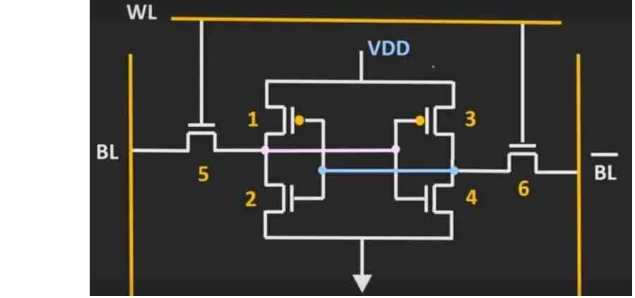
- Two transistors, i.e. transistor 5 & 6, are pass transistors which are connected to the bit lines. They are used during the read-write operations to manage the availability of a memory cell.
- The remaining four transistors (i.e. Transistors 1, 2, 3 and 4) form two cross-coupled inverters. Thus, transistors 1 and 2 forms one CMOS inverter pair, and the remaining two transistors, 3 and 4, form the other CMOS inverter pair.
- Due to the complex architecture of the SRAM, it costs more for manufacturing this memory.
- Due to the high speed of operation, SRAM is used for cache memory and as part of the digital-to-analog converter on video cards. It is also found in CDs, printers, routers, DVDs and digital cameras.
Read Only Memory(ROM)
- ROM is non Voletile memory. It holds programs and data permanently even when computer and device is switched off.
- Data can be read by the CPU in any order so ROM is also direct access.
- The contents of ROM are fixed at the time of manufacture.
- Stores a program called the bootstrap loader that helps start up the computer.
- Access time of between 10 and 50 nanoseconds .
Data Converters
- All the real world quantities are analog in nature. We can represent these quantities electrically as analog signals. An analog signal is a time varying signal that has any number of values (variations) for a given time slot.
- In contrast to this, a digital signal varies suddenly from one level to another level and will have only finite number of values (variations) for a given time slot.
- The electronic circuits, which can be operated with analog signals are called as analog circuits. Similarly, the electronic circuits, which can be operated with digital signals are called as digital circuits.
- In digital electronics, a Data Converter is a circuit that converts analog to digital or vice-versa. It means a data converter is an electronic circuit that converts data of one form to another.
- There are two types of data converters −
- Analog to Digital Converter
- Digital to Analog Converter
Analog to Digital Converters(ADC)
- An analog to digital converter takes an analog input signal and after certain amount of time produces a digital output code which represents the analog input.
- A pure analog signal is more accurate than adigital system. The analog to digital conversion process is more complex and time consuming than DAC process.
- Following are the most commonly used methods for Analog to Digital conversion.
- Digital Ramp A/D converter
- Successive Approximate A/D converter
- Single slope A/D converter
- Dual slope A/D converter
- Voltage to frequency A/D converter
- A/D converter

Digital to Analog converters (DAC)
- Digital to analog conversion is the process of taking a value represented in digital code and converting it to a signal which is proportional to the digital value.
- Typically, the stuff that you store on your computer or any other technical device is saved in the binary form- a set of 1s and 0s that encode some information.
- The digital output from the technical device is connected to a DAC, which converts it to a proportional analog signal.
- There are two methods commonly used for digital to analog conversion
- Weighted Resistors method .
- R-2R ladder network method.

- .
Weighted Resistors DAC
- It is the type of DAC that transforms a particular binary code into an equivalent analog signal. If the binary code given at the input terminal is altered continuously, the output will change as well.

-
R-2R ladder network DAC
- R-2R configuration is a simple arrangement that consists of parallel and series resistors connected in the cascaded form to an operational amplifier..
- This type of converter has only two values of resistors R and 2R. The conversion speed reduces in this type due to parasitic capacitance.
- It is the simplest type of DAC where the switch between ground and inverting input of the op-amp is controlled by the input bit.
- The gain Av and output voltage Vo of R-2R Ladder DAC is given by the equation:
- 3-bit R-2R Ladder digital to analog converter circuit is shown below.
Av = -R/2R = -1/2
Vo = VR.(RF/R )[ ]

-